


Atlantis Support · Installation guide
Atlantis Mini Retrofit Kit: AUTO kit
For TEC boxes WITH an Auto Control switch
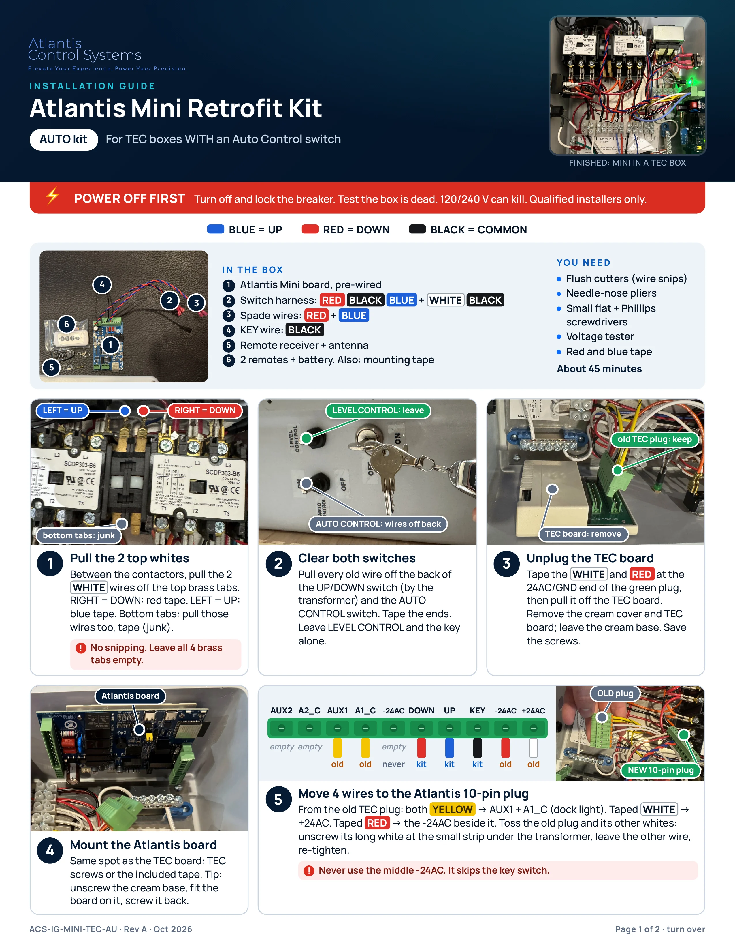
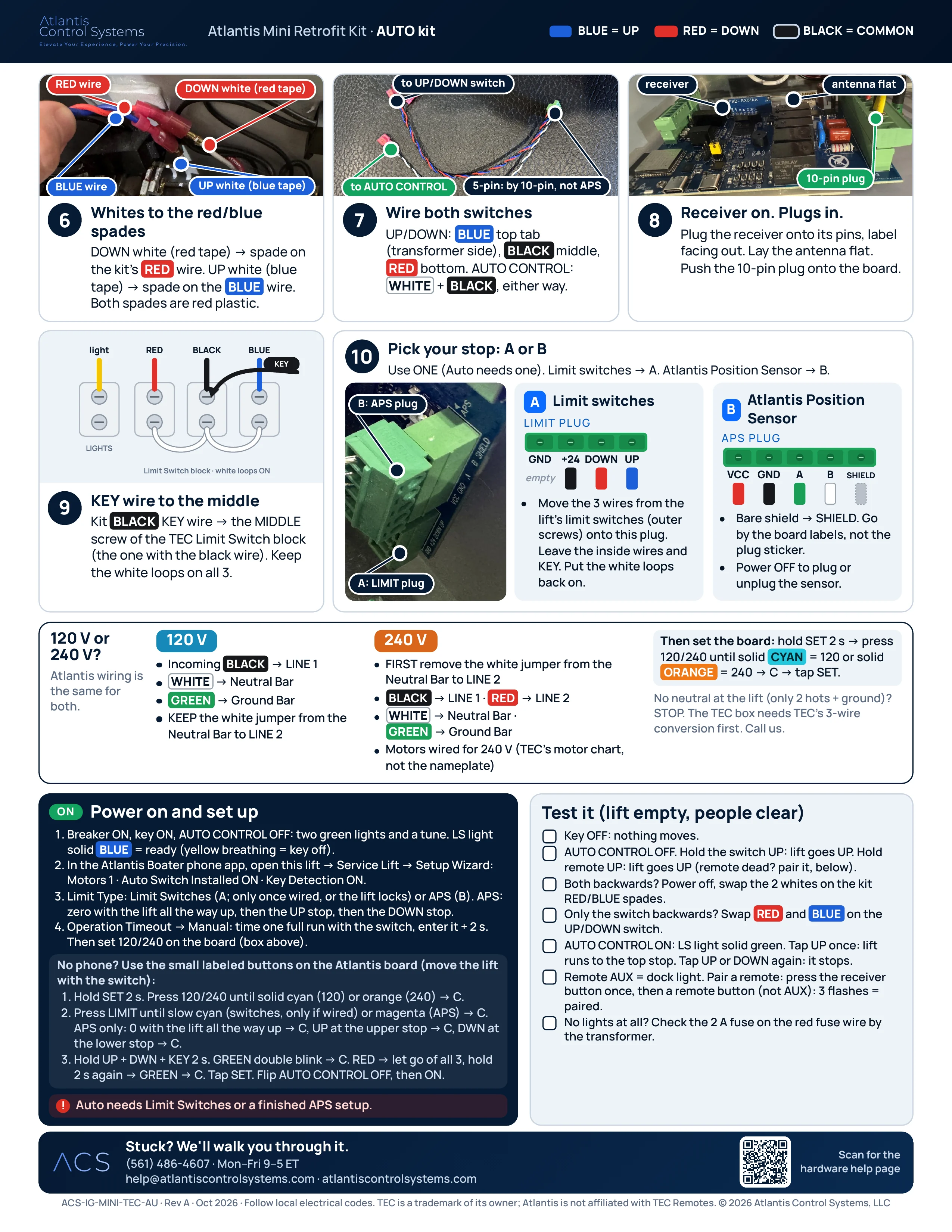
The approved two-page install guide, as printed. Select a page to open the full-quality PDF, then zoom in on any photo or label. About 45 minutes.
PDF · 2 pages · 2.9 MB · ACS-IG-MINI-TEC-AU · Rev A · Oct 2026
- BLUE = UP
- RED = DOWN
- BLACK = COMMON
The install guide: AUTO kit
Not sure which kit? No-AUTO kit: TEC box with NO Auto switch (TEC II L/S). AUTO kit: TEC box WITH an Auto Control switch.
Text version
Step by step
The same steps as the printed AUTO kit guide, written out for small screens and screen readers.
In the box
- Atlantis Mini board, pre-wired
- Switch harness: RED BLACK BLUE + WHITE BLACK
- Spade wires: RED + BLUE
- KEY wire: BLACK
- Remote receiver + antenna
- 2 remotes + battery. Also: mounting tape
You need
- Flush cutters (wire snips)
- Needle-nose pliers
- Small flat + Phillips screwdrivers
- Voltage tester
- Red and blue tape
About 45 minutes
Step 1: Pull the 2 top whites
Between the contactors, pull the 2 WHITE wires off the top brass tabs. RIGHT = DOWN: red tape. LEFT = UP: blue tape. Bottom tabs: pull those wires too, tape (junk).
No snipping. Leave all 4 brass tabs empty.
Step 2: Clear both switches
Pull every old wire off the back of the UP/DOWN switch (by the transformer) and the AUTO CONTROL switch. Tape the ends. Leave LEVEL CONTROL and the key alone.
Step 3: Unplug the TEC board
Tape the WHITE and RED at the 24AC/GND end of the green plug, then pull it off the TEC board. Remove the cream cover and TEC board; leave the cream base. Save the screws.
Step 4: Mount the Atlantis board
Same spot as the TEC board: TEC screws or the included tape. Tip: unscrew the cream base, fit the board on it, screw it back.
Step 5: Move 4 wires to the Atlantis 10-pin plug
From the old TEC plug: both YELLOW → AUX1 + A1_C (dock light). Taped WHITE → +24AC. Taped RED → the -24AC beside it. Toss the old plug and its other whites: unscrew its long white at the small strip under the transformer, leave the other wire, re-tighten.
Never use the middle -24AC. It skips the key switch.
| Pin | Wire | From |
|---|---|---|
| AUX2 | empty | Leave empty |
| A2_C | empty | Leave empty |
| AUX1 | YELLOW | From the old TEC plug |
| A1_C | YELLOW | From the old TEC plug |
| -24AC | empty | Never use: it skips the key switch |
| DOWN | RED | Atlantis kit wire |
| UP | BLUE | Atlantis kit wire |
| KEY | BLACK | Atlantis kit wire |
| -24AC | RED | From the old TEC plug (taped) |
| +24AC | WHITE | From the old TEC plug (taped) |
Step 6: Whites to the red/blue spades
DOWN white (red tape) → spade on the kit's RED wire. UP white (blue tape) → spade on the BLUE wire. Both spades are red plastic.
Step 7: Wire both switches
UP/DOWN: BLUE top tab (transformer side), BLACK middle, RED bottom. AUTO CONTROL: WHITE + BLACK, either way.
Step 8: Receiver on. Plugs in.
Plug the receiver onto its pins, label facing out. Lay the antenna flat. Push the 10-pin plug onto the board.
Step 9: KEY wire to the middle
Kit BLACK KEY wire → the MIDDLE screw of the TEC Limit Switch block (the one with the black wire). Keep the white loops on all 3.
Step 10: Pick your stop: A or B
Use ONE (Auto needs one). Limit switches → A. Atlantis Position Sensor → B.
A · Limit switches: LIMIT plug
| Pin | Wire | From |
|---|---|---|
| GND | empty | Leave empty |
| +24 | BLACK | Lift's limit switch wire |
| DOWN | RED | Lift's limit switch wire |
| UP | BLUE | Lift's limit switch wire |
- Move the 3 wires from the lift's limit switches (outer screws) onto this plug. Leave the inside wires and KEY. Put the white loops back on.
- Normally closed (NC) limit switches only.
B · Atlantis Position Sensor: APS plug
| Pin | Wire | From |
|---|---|---|
| VCC | RED | Atlantis Position Sensor cable |
| GND | BLACK | Atlantis Position Sensor cable |
| A | GREEN | Atlantis Position Sensor cable |
| B | WHITE | Atlantis Position Sensor cable |
| SHIELD | bare shield | Atlantis Position Sensor cable |
- Bare shield → SHIELD. Go by the board labels, not the plug sticker.
- Power OFF to plug or unplug the sensor.
120 V or 240 V?
Atlantis wiring is the same for both.
120 V
- Incoming BLACK → LINE 1
- WHITE → Neutral Bar
- GREEN → Ground Bar
- KEEP the white jumper from the Neutral Bar to LINE 2
240 V
- FIRST remove the white jumper from the Neutral Bar to LINE 2
- BLACK → LINE 1 · RED → LINE 2
- WHITE → Neutral Bar · GREEN → Ground Bar
- Motors wired for 240 V (TEC's motor chart, not the nameplate)
Then set the board: hold SET 2 s → press 120/240 until solid CYAN = 120 or solid ORANGE = 240 → C → tap SET.
No neutral at the lift (only 2 hots + ground)? STOP. The TEC box needs TEC's 3-wire conversion first. Call us.
Power on and set up
- Breaker ON, key ON, AUTO CONTROL OFF: two green lights and a tune. LS light solid BLUE = ready (yellow breathing = key off).
- In the Atlantis Boater phone app, open this lift → Service Lift → Setup Wizard: Motors 1 · Auto Switch Installed ON · Key Detection ON.
- Limit Type: Limit Switches (A; only once wired, or the lift locks) or APS (B). APS: zero with the lift all the way up, then the UP stop, then the DOWN stop.
- Operation Timeout → Manual: time one full run with the switch, enter it + 2 s. Then set 120/240 on the board (box above).
No phone? Use the small labeled buttons on the Atlantis board (move the lift with the switch):
- Hold SET 2 s. Press 120/240 until solid cyan (120) or orange (240) → C.
- Press LIMIT until slow cyan (switches, only if wired) or magenta (APS) → C. APS only: 0 with the lift all the way up → C, UP at the upper stop → C, DWN at the lower stop → C.
- Hold UP + DWN + KEY 2 s. GREEN double blink → C. RED → let go of all 3, hold 2 s again → GREEN → C. Tap SET. Flip AUTO CONTROL OFF, then ON.
Auto needs Limit Switches or a finished APS setup.
Test it (lift empty, people clear)
- Key OFF: nothing moves.
- AUTO CONTROL OFF. Hold the switch UP: lift goes UP. Hold remote UP: lift goes UP (remote dead? pair it, below).
- Both backwards? Power off, swap the 2 whites on the kit RED/BLUE spades.
- Only the switch backwards? Swap RED and BLUE on the UP/DOWN switch.
- AUTO CONTROL ON: LS light solid green. Tap UP once: lift runs to the top stop. Tap UP or DOWN again: it stops.
- Remote AUX = dock light. Pair a remote: press the receiver button once, then a remote button (not AUX): 3 flashes = paired.
- No lights at all? Check the 2 A fuse on the red fuse wire by the transformer.
Stuck? We'll walk you through it.
(561) 486-4607 · Mon–Fri 9–5 ET · [email protected]
Related guides
ACS-IG-MINI-TEC-AU · Rev A · Oct 2026 · Follow local electrical codes. TEC is a trademark of its owner; Atlantis is not affiliated with TEC Remotes. © 2026 Atlantis Control Systems, LLC
Open the AUTO kit PDF(opens in a new tab)Was this article helpful?
Tell us whether this answered your question.