


Atlantis Support · Installation guide
Atlantis Mini Retrofit Kit: No-AUTO kit
For TEC boxes with NO Auto switch (TEC II L/S)
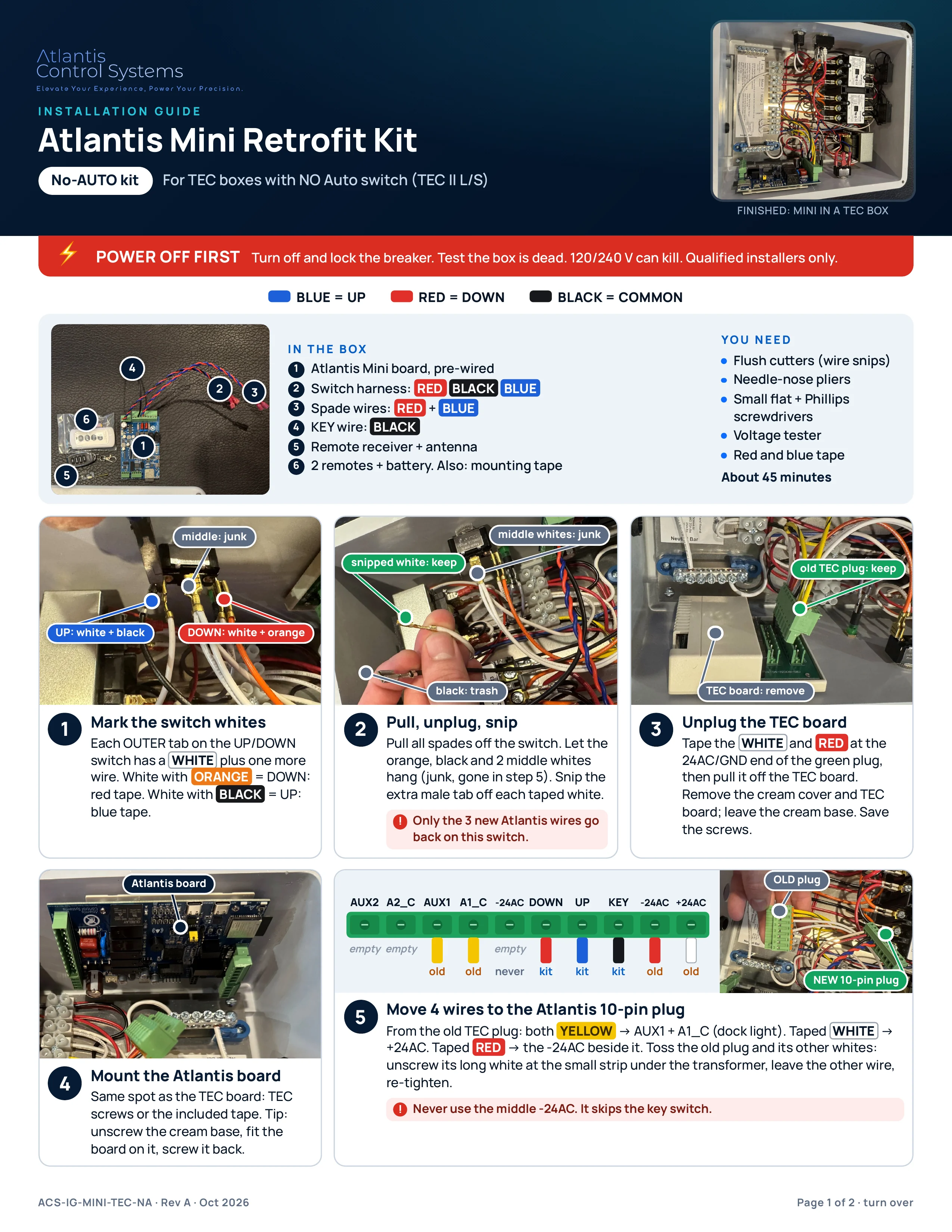
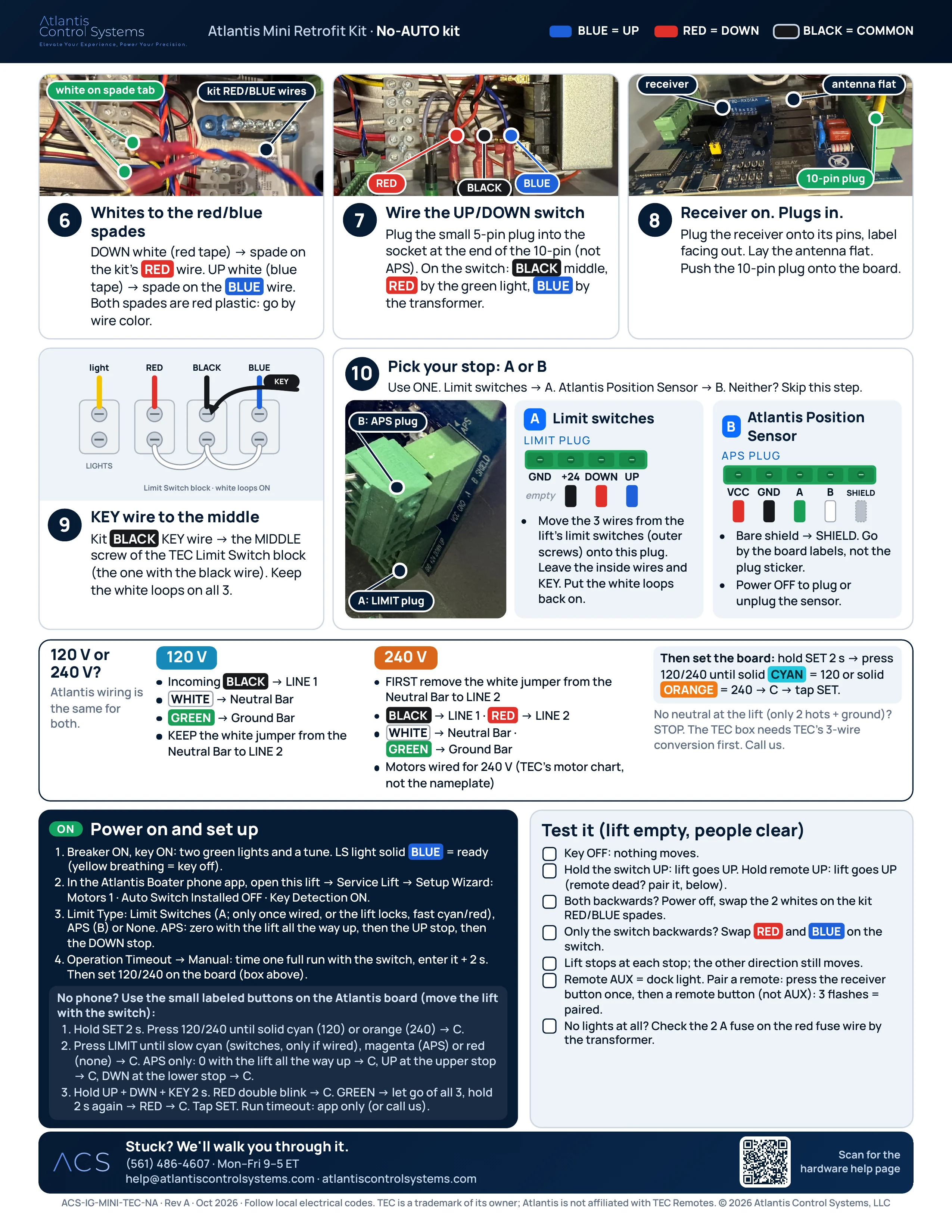
The approved two-page install guide, as printed. Select a page to open the full-quality PDF, then zoom in on any photo or label. About 45 minutes.
PDF · 2 pages · 2.9 MB · ACS-IG-MINI-TEC-NA · Rev A · Oct 2026
- BLUE = UP
- RED = DOWN
- BLACK = COMMON
The install guide: No-AUTO kit
Not sure which kit? No-AUTO kit: TEC box with NO Auto switch (TEC II L/S). AUTO kit: TEC box WITH an Auto Control switch.
Text version
Step by step
The same steps as the printed No-AUTO kit guide, written out for small screens and screen readers.
In the box
- Atlantis Mini board, pre-wired
- Switch harness: RED BLACK BLUE
- Spade wires: RED + BLUE
- KEY wire: BLACK
- Remote receiver + antenna
- 2 remotes + battery. Also: mounting tape
You need
- Flush cutters (wire snips)
- Needle-nose pliers
- Small flat + Phillips screwdrivers
- Voltage tester
- Red and blue tape
About 45 minutes
Step 1: Mark the switch whites
Each OUTER tab on the UP/DOWN switch has a WHITE plus one more wire. White with ORANGE = DOWN: red tape. White with BLACK = UP: blue tape.
Step 2: Pull, unplug, snip
Pull all spades off the switch. Let the orange, black and 2 middle whites hang (junk, gone in step 5). Snip the extra male tab off each taped white.
Only the 3 new Atlantis wires go back on this switch.
Step 3: Unplug the TEC board
Tape the WHITE and RED at the 24AC/GND end of the green plug, then pull it off the TEC board. Remove the cream cover and TEC board; leave the cream base. Save the screws.
Step 4: Mount the Atlantis board
Same spot as the TEC board: TEC screws or the included tape. Tip: unscrew the cream base, fit the board on it, screw it back.
Step 5: Move 4 wires to the Atlantis 10-pin plug
From the old TEC plug: both YELLOW → AUX1 + A1_C (dock light). Taped WHITE → +24AC. Taped RED → the -24AC beside it. Toss the old plug and its other whites: unscrew its long white at the small strip under the transformer, leave the other wire, re-tighten.
Never use the middle -24AC. It skips the key switch.
| Pin | Wire | From |
|---|---|---|
| AUX2 | empty | Leave empty |
| A2_C | empty | Leave empty |
| AUX1 | YELLOW | From the old TEC plug |
| A1_C | YELLOW | From the old TEC plug |
| -24AC | empty | Never use: it skips the key switch |
| DOWN | RED | Atlantis kit wire |
| UP | BLUE | Atlantis kit wire |
| KEY | BLACK | Atlantis kit wire |
| -24AC | RED | From the old TEC plug (taped) |
| +24AC | WHITE | From the old TEC plug (taped) |
Step 6: Whites to the red/blue spades
DOWN white (red tape) → spade on the kit's RED wire. UP white (blue tape) → spade on the BLUE wire. Both spades are red plastic: go by wire color.
Step 7: Wire the UP/DOWN switch
Plug the small 5-pin plug into the socket at the end of the 10-pin (not APS). On the switch: BLACK middle, RED by the green light, BLUE by the transformer.
Step 8: Receiver on. Plugs in.
Plug the receiver onto its pins, label facing out. Lay the antenna flat. Push the 10-pin plug onto the board.
Step 9: KEY wire to the middle
Kit BLACK KEY wire → the MIDDLE screw of the TEC Limit Switch block (the one with the black wire). Keep the white loops on all 3.
Step 10: Pick your stop: A or B
Use ONE. Limit switches → A. Atlantis Position Sensor → B. Neither? Skip this step.
A · Limit switches: LIMIT plug
| Pin | Wire | From |
|---|---|---|
| GND | empty | Leave empty |
| +24 | BLACK | Lift's limit switch wire |
| DOWN | RED | Lift's limit switch wire |
| UP | BLUE | Lift's limit switch wire |
- Move the 3 wires from the lift's limit switches (outer screws) onto this plug. Leave the inside wires and KEY. Put the white loops back on.
- Normally closed (NC) limit switches only.
B · Atlantis Position Sensor: APS plug
| Pin | Wire | From |
|---|---|---|
| VCC | RED | Atlantis Position Sensor cable |
| GND | BLACK | Atlantis Position Sensor cable |
| A | GREEN | Atlantis Position Sensor cable |
| B | WHITE | Atlantis Position Sensor cable |
| SHIELD | bare shield | Atlantis Position Sensor cable |
- Bare shield → SHIELD. Go by the board labels, not the plug sticker.
- Power OFF to plug or unplug the sensor.
120 V or 240 V?
Atlantis wiring is the same for both.
120 V
- Incoming BLACK → LINE 1
- WHITE → Neutral Bar
- GREEN → Ground Bar
- KEEP the white jumper from the Neutral Bar to LINE 2
240 V
- FIRST remove the white jumper from the Neutral Bar to LINE 2
- BLACK → LINE 1 · RED → LINE 2
- WHITE → Neutral Bar · GREEN → Ground Bar
- Motors wired for 240 V (TEC's motor chart, not the nameplate)
Then set the board: hold SET 2 s → press 120/240 until solid CYAN = 120 or solid ORANGE = 240 → C → tap SET.
No neutral at the lift (only 2 hots + ground)? STOP. The TEC box needs TEC's 3-wire conversion first. Call us.
Power on and set up
- Breaker ON, key ON: two green lights and a tune. LS light solid BLUE = ready (yellow breathing = key off).
- In the Atlantis Boater phone app, open this lift → Service Lift → Setup Wizard: Motors 1 · Auto Switch Installed OFF · Key Detection ON.
- Limit Type: Limit Switches (A; only once wired, or the lift locks, fast cyan/red), APS (B) or None. APS: zero with the lift all the way up, then the UP stop, then the DOWN stop.
- Operation Timeout → Manual: time one full run with the switch, enter it + 2 s. Then set 120/240 on the board (box above).
No phone? Use the small labeled buttons on the Atlantis board (move the lift with the switch):
- Hold SET 2 s. Press 120/240 until solid cyan (120) or orange (240) → C.
- Press LIMIT until slow cyan (switches, only if wired), magenta (APS) or red (none) → C. APS only: 0 with the lift all the way up → C, UP at the upper stop → C, DWN at the lower stop → C.
- Hold UP + DWN + KEY 2 s. RED double blink → C. GREEN → let go of all 3, hold 2 s again → RED → C. Tap SET. Run timeout: app only (or call us).
Test it (lift empty, people clear)
- Key OFF: nothing moves.
- Hold the switch UP: lift goes UP. Hold remote UP: lift goes UP (remote dead? pair it, below).
- Both backwards? Power off, swap the 2 whites on the kit RED/BLUE spades.
- Only the switch backwards? Swap RED and BLUE on the switch.
- Lift stops at each stop; the other direction still moves.
- Remote AUX = dock light. Pair a remote: press the receiver button once, then a remote button (not AUX): 3 flashes = paired.
- No lights at all? Check the 2 A fuse on the red fuse wire by the transformer.
Stuck? We'll walk you through it.
(561) 486-4607 · Mon–Fri 9–5 ET · [email protected]
Related guides
ACS-IG-MINI-TEC-NA · Rev A · Oct 2026 · Follow local electrical codes. TEC is a trademark of its owner; Atlantis is not affiliated with TEC Remotes. © 2026 Atlantis Control Systems, LLC
Open the No-AUTO kit PDF(opens in a new tab)Was this article helpful?
Tell us whether this answered your question.